- Kataloge
- ATESTEO GmbH & Co. KG
- Handbuch Messlenkrad (EN)
Handbuch Messlenkrad (EN)
1 /17Seiten
Handbuch Messlenkrad (EN)
1 /17Seiten
Katalogauszüge

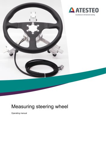
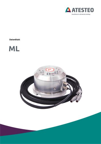
Measuring steering wheel Operating manual
Katalog auf Seite 1 öffnen
Measuring steering wheel V 2.1 05/2022 Change log: V2.1 03.05.2022: “Shunt calibration” replaced by “test signal” Installation without adapter added Difference between measurement body and adapter kit explained more clearly Pictures of measurement body and cover added V2.0 08.2020: First updated version Your contact for service requests ATESTEO GmbH & Co. KG Konrad-Zuse-Str. 3 52477 Alsdorf Germany T +49 2404 9870-580 [email protected] www.atesteo.com ATESTEO GmbH & Co. KG Measuring steering wheel – V 2.1 – 05/2
Katalog auf Seite 2 öffnen
Measuring steering wheel - V 2.1 - 05/2022
Katalog auf Seite 3 öffnen
Product description Product description The product “measuring steering wheel” is used for installation inside of a vehicle. With an optional adapter kit it is mounted on top of the existing vehicle steering wheel. Without that adapter kit it can be mounted on the steering system after removing the original vehicle steering wheel. The “measuring steering wheel” measures the applied steering torque and optionally the rotation angle. The product must be handled as measurement sensor. Misuse and wrong handling can damage the sensor or lead to wrong measurement results. The measuring steering wheel...
Katalog auf Seite 4 öffnen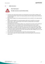
Product description AATESTEO Risk of fatal injuries! All safety instructions must be followed strictly. • The airbag of the original steering wheel must be deactivated and removed before installation of the measuring steering wheel. Usage of the measuring steering wheel with airbag is strictly prohibited and can lead to death. • When using the adapter kit, the measuring steering wheel must be mounted fix on the original steering wheel. • Without using the adapter kit, the measuring steering wheel must be mounted fix on the original steering system. A safe mounting solution must be chosen by operator...
Katalog auf Seite 5 öffnen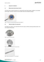
Equipment installation Equipment installation Measurement body (torque sensor) The torque sensor contains the electronic for measuring the torque (strain gauges, amplifiers, and controller) and the angle. The sensor consist of a rotor and stator which are connected by bearings. Figure 1 Torque sensor (measuring steering wheel) without adapter kit Optional adapter kit components The adapter kit is optional. The components of this kit are used to install the measuring steering wheel on top of the original steering wheel. Figure 2 Cover for the torque sensor Figure 3 Connector disk (attached to...
Katalog auf Seite 6 öffnen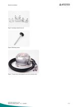
Equipment installation Figure 5 Clamping material set (3x) Figure 6 Mounting screws Figure 7 Torque sensor (with attached cover and connector disk) ATESTEO GmbH & Co. KG Measuring steering wheel – V 2.1 – 05/2022
Katalog auf Seite 7 öffnen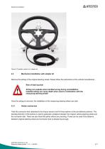
Equipment installation Figure 8 Complete system incl. adapter kit Mechanical installation with adapter kit Remove the airbag of the original steering wheel. Please follow the instructions of the vehicle manufacturer. Risk of fatal injuries! Airbag can explode when handled wrong during uninstallation. Installed airbag can cause death when used in combination with the measuring steering wheel! Once the airbag is removed, the installation of the measuring steering wheel can start. 2.3.1 Holder mechanism Take the connector disk (attached to the torque sensor) and fix three splines at the pre-defined...
Katalog auf Seite 8 öffnen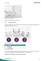
Equipment installation AATESTEO Use two screws of type M6x16 to fix one spline. The clamping mechanism is used to fix the previously mentioned holder with the original steering wheel. First take the three parts shown in Figure 10. o © o Figure 10 Clamping components Table 1 Clamping components This set must be installed three times with 120° angle between each set. It’s a good way to do the assembly with two persons. One person is holding the parts, the other one is fixing the screws. Measuring steering wheel - V 2.1 - 05/2022
Katalog auf Seite 9 öffnen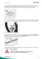
Equipment installation Take the “fixing block” and hold it behind the original steering wheel. Attach the “Round connector” to the “Fixing block” at the front side of the steering wheel. Place the “Flat connector” on top of the rear side of the “Round connector”. Make sure the track in both parts are combined. They will clamp the spline later. Figure 11 Track on the clamping material Use the “mounting screws” (see Figure 6) to fix the set together. They must be installed with the black handle on the backside of the steering wheel. Before tightening well, insert a spline into the track for each...
Katalog auf Seite 10 öffnen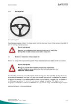
Equipment installation Steering wheel Figure 14 Steering wheel Place the steering wheel on top of the torque sensor (onto the cover, see Figure 2). Use screws of type M6x10 to fix the steering wheel (six screws). Risk of fatal injuries! If screws are not tightened well, steering control can be lost during driving! Risk of death. Check screws before every drive. Mechanical installation without adapter kit Remove the airbag of the original steering wheel. Please follow the instructions of the vehicle manufacturer. Risk of fatal injuries! Airbag can explode when handled wrong during uninstallation....
Katalog auf Seite 11 öffnen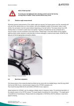
Equipment installation Risk of fatal injuries! If screws are not tightened well, steering control can be lost during driving! Risk of death. Check screws before every drive. Rotation angle measurement Whenever precise measurements of the rotation angle are required, the torque sensor must be connected with a fix part of the vehicle body (e.g. front window). Since the installation position of the sensor varies in each vehicle, the connection must be custom-tailored depending on the test vehicle. The torque sensor has a M6 winding where a connection system has to be applied. Typically a threaded...
Katalog auf Seite 12 öffnen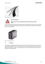
Equipment installation Figure 16 Plugs at the torque sensor Risk of fatal injuries! Make sure the wires do not influence the driver during driving . Risk of death. Fix the wires at positions, where they do not influence the driver. Make sure the wires are not in tension since movement of the steering wheel will rotate the torque sensor few centimetres (if mounted without connection system to the vehicle body). Figure 17 VETAS evaluation unit Test signal The test signal is triggered by the terminal. Please connect the VETAS 3 by serial port to your computer and start the terminal program (included...
Katalog auf Seite 13 öffnenAlle Kataloge und technischen Broschüren von ATESTEO GmbH & Co. KG
 Datenblatt DF4 ibex
21 Seiten
 Datenblatt DF5 ibex
21 Seiten
 Datenblatt F4xS
21 Seiten
 Datenblatt DF5 dual
23 Seiten
 Datenblatt DF4 dual
23 Seiten
 Datenblatt DF3 dual
23 Seiten
 Datenblatt DF2 dual
23 Seiten
 Datenblatt DF1 dual
23 Seiten
 Handbuch CapSync HVT
68 Seiten
 Datenblatt CapSync HVT
7 Seiten
 Handbuch IRTS-Serie
124 Seiten
 Datenblatt IRTS-P
11 Seiten
 Handbuch VETAS 3 (EN)
30 Seiten
 Handbuch VECTO (EN)
26 Seiten
 Datenblatt Messlenkrad
9 Seiten
 Handbuch DST-Serie (EN)
69 Seiten
 Datenblatt DST-Serie
13 Seiten
 Datenblatt TiS Z50
20 Seiten
 Handbuch T-Serie
132 Seiten
 Datenblatt TeS Z50
21 Seiten
 Handbuch RT11-Serie
132 Seiten
 Datenblatt RT11eS-B
20 Seiten
 Datenblatt RT11eS
17 Seiten
 Handbuch HSTTeS-Serie
132 Seiten
 Datenblatt HSTTeS-Serie
20 Seiten
 Datenblatt F23 RTS
7 Seiten
 Datenblatt F3 RTS
7 Seiten
 Datenblatt F5xS
18 Seiten
 Datenblatt F34xS
21 Seiten
 Datenblatt F3xS
27 Seiten
 Datenblatt F23xS
21 Seiten
 Handbuch Fx-Serie
132 Seiten
 Datenblatt F2xS
35 Seiten
 Datenblatt F1xS
27 Seiten
 Datenblatt F0xS
51 Seiten
 Datenblatt F0xS-SV
27 Seiten
 Datenblatt DF RTS
11 Seiten
 Datenblatt DF plus HS
20 Seiten
 Handbuch DF plus-Serie
132 Seiten
 Datenblatt DF plus-Serie
41 Seiten
 Handbuch DF dual-Serie
132 Seiten
 Handbuch DF ibex-Serie
132 Seiten
 Datenblatt DF3 ibex
21 Seiten
 Datenblatt DF2 ibex
21 Seiten
 Datenblatt DF1 ibex
21 Seiten
- Drehmomentsensor
- Dynamischer Drehmomentsensor
- Rotations-Drehmomentsensor
- Analoger Drehmomentsensor
- Dehnungsmessstreifen-Drehmomentsensor
- DC-Drehmomentsensor
- Kontaktloser Drehmomentsensor
- Digitaler Drehmomentsensor
- Hochpräzisions-Drehmomentsensor
- Drehmomentsensor mit Flanschanschluss
- Modularer Temperaturkontrolle
- Drehmomentsensor mit Spannungsausgang
- Kompakter Drehmomentsensor
- Drehmomentsensor / 12 VDC
- USB-Drehmomentsensor
- Flanschmontage-Drehmomentsensor
- Drehmomentsensor nach Maß
- Drehmomentsensor für Prüfstände
- Drehmomentsensor für Automobilanwendungen
- Drehmomentsensor / 24 VDC