- Kataloge
- ATESTEO GmbH & Co. KG
- Handbuch VETAS 3 (EN)
Handbuch VETAS 3 (EN)
1 /30Seiten
Handbuch VETAS 3 (EN)
1 /30Seiten
Katalogauszüge
Operation manual Evaluation unit VETAS 3 V3 Vehicle measuring system Dear customer, Before leaving our company, every unit is tested by extensive function and quality examinations, which guarantee that the system complies with the stated specifications. Nevertheless, should there be any problem, please contact us. Before shipping a system, the serial number of each component of your configuration is registered by our company, so that an individual and short-term support can be guaranteed. It is understood that we will inform you about innovations and modifications of the system. Warranty In case of intended use, ATESTEO will issue a guarantee of 12 months according to warranty period regulated by law. In case of damages caused by improper use warranty claims cannot be submitted.
Katalog auf Seite 1 öffnen
AATESTEO Excellence in drivetrain testing
Katalog auf Seite 2 öffnen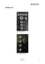
Excellence in drivetrain testing
Katalog auf Seite 3 öffnen
Excellence in drivetrain testing
Katalog auf Seite 4 öffnen
Excellence in drivetrain testing
Katalog auf Seite 5 öffnen
Excellence in drivetrain testing In this manual, you will find all steps to be taken for electrical and Software start-up of ATESTEO products, which are compatible with VETAS 3 (such as vehicle telemetry system or measuring steering wheel). This manual is applicable for the following types of measuring systems: • 1x torque, 1x temperature (rotor electronic temperature) • 2x temperature (1x thermocouple, 1x rotor electronic temperature) For setting-up the corresponding measuring system, refer to the appropriate appendix. Each measuring system is thoroughly checked before delivery to its technical...
Katalog auf Seite 6 öffnen
Excellence in drivetrain testing The evaluation unit VETAS 3 V3 provides all necessary supply interfaces for running the compatible ATESTEO measurement systems. The USB interface can be used for external monitoring and controlling by the VECTO software package. Necessary software updates and an extra data connection can be linked by this USB serial interface too. All measurement systems work contactless and are maintenance-free. The data transmission can be realized by a frequency-modulated infrared or by an inductive transmitter. The electrical power supply of the rotating electronic circuit...
Katalog auf Seite 7 öffnen
Excellence in drivetrain testing o Analog scaling (percentage of rated torque ^ full-scale) o 500Hz analog output filter
Katalog auf Seite 8 öffnen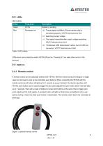
Excellence in drivetrain testing CAN errors can be reset by switch VETAS off and on. Pressing ‘E’ can reset other errors in the terminal. A remote control can be optionally ordered with VETAS. With the remote control, the torque or angle value can be reset to zero by two individual push buttons. When connecting the VETAS with the remote control, each button will light up for 1 second as power indicator. During the operation with VETAS, each button can be used to trigger the zero point adjustment (zero reset). Each reset will take up to 7 seconds. Wait until a reset is finished or press both buttons...
Katalog auf Seite 9 öffnen
3 Safety Instructions Before starting up and maintenance or in case of other operations at the measurement system attention should be paid to the following instructions: Follow all safety instructions and directions denoted in the operation manual. Make sure that every precaution will be taken. It is a necessity that all safety appliances are functional attached to the measuring device. Only in this way, a safe and successful operation is guaranteed. Reference to additional standards: Low Voltage Directive 73/23/EWG, Electromagnetic Compatibility Directive 89/336/EWG and the harmonized standards...
Katalog auf Seite 10 öffnen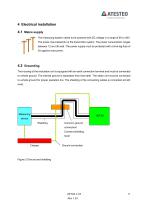
4 Electrical installation 4.1 Mains supply The measuring system needs to be powered with DC voltage in a range of 9V to 36V. The power input depends on the transmitter system. The power consumption ranges between 12 and 36 watt. The power supply must be protected with a time-lag fuse of 3A against overcurrent. 4.2 Grounding The housing of the evaluation unit is equipped with an earth connection terminal and must be connected to vehicle ground. The internal ground is separated from that earth. The stator unit must be connected to vehicle ground for proper operation too. The shielding of the connecting...
Katalog auf Seite 11 öffnen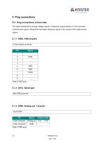
Excellence in drivetrain testing The signal transferred by analog voltage Outputs or frequency Outputs depend on the connected measurement system. Please find information about the signal in the manual of the measurement system. D-Sub female connector
Katalog auf Seite 12 öffnen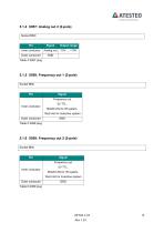
Excellence in drivetrain testing
Katalog auf Seite 13 öffnen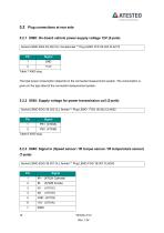
Excellence in drivetrain testing Socket LEMO ERA.2S.302.CLL female/male ** Plug LEMO FFP.2S.302.CLAC72
Katalog auf Seite 14 öffnen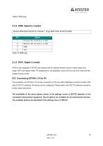
Excellence in drivetrain testing Socket LEMO EGG.1 B.304.CLL female ** Plug LEMO FGG.1B.304 CLAD52 X970 is only equipped if VETAS was ordered with an optional remote control to reset torque and angle. X970 will replace X960. Pin assignment is not published, since X970 is only to be used with the related remote control. The evaluation unit VETAS 3 V3 can be connected to a PC via a Mini-USB slave connector socket. With help of VECTO software, the device can be configured. Please refer to the VECTO software manual for further setup instructions. The availability of the setup options shown in the...
Katalog auf Seite 15 öffnen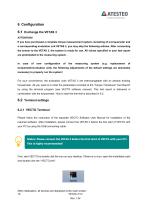
Excellence in drivetrain testing If you have purchased a complete torque measurement system consisting of a torquemeter and a corresponding evaluation unit VETAS 3, you may skip the following articles. After connecting the sensor to the VETAS 3, the system is ready for use. All values specified in your test report are preinstalled to the measuring system. In case of new configuration of the measuring system (e.g. replacement of torquemeter/evaluation unit), the following adjustments of the default settings are absolutely necessary to properly run the system! For your convenience, the evaluation...
Katalog auf Seite 16 öffnen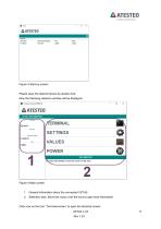
Figure 3 Start-up screen Please open the desired device by double click. Now the following selection window will be displayed: Figure 4 Main screen 1. General information about the connected VETAS 2. Selection area. Move the cursor over the icons to get more information Click now on the icon “Terminal-screen” to open the terminal screen: VETAS 3 V3 Rev.1.34
Katalog auf Seite 17 öffnenAlle Kataloge und technischen Broschüren von ATESTEO GmbH & Co. KG
 Datenblatt DF4 ibex
21 Seiten
 Datenblatt DF5 ibex
21 Seiten
 Datenblatt F4xS
21 Seiten
 Datenblatt DF5 dual
23 Seiten
 Datenblatt DF4 dual
23 Seiten
 Datenblatt DF3 dual
23 Seiten
 Datenblatt DF2 dual
23 Seiten
 Datenblatt DF1 dual
23 Seiten
 Handbuch CapSync HVT
68 Seiten
 Datenblatt CapSync HVT
7 Seiten
 Handbuch IRTS-Serie
124 Seiten
 Datenblatt IRTS-P
11 Seiten
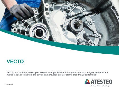 Handbuch VECTO (EN)
26 Seiten
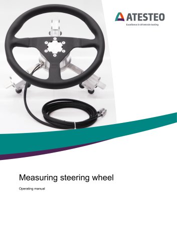 Handbuch Messlenkrad (EN)
17 Seiten
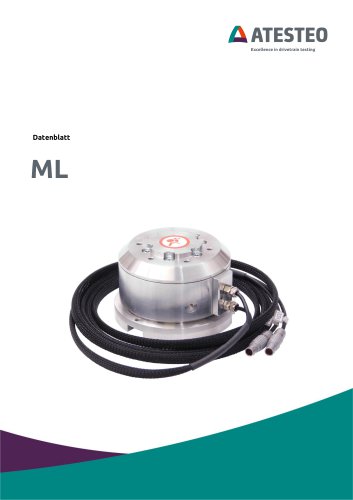 Datenblatt Messlenkrad
9 Seiten
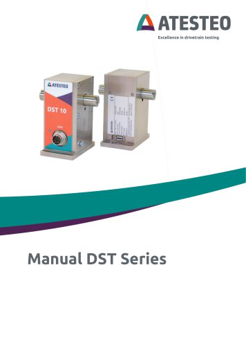 Handbuch DST-Serie (EN)
69 Seiten
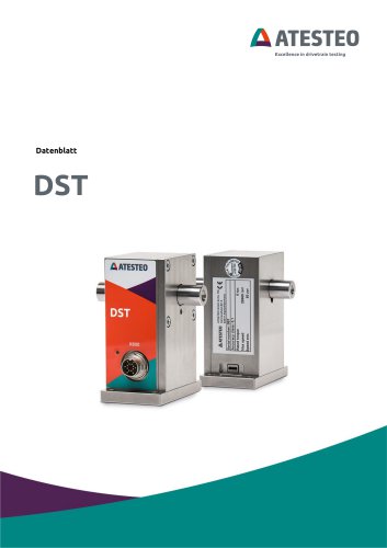 Datenblatt DST-Serie
13 Seiten
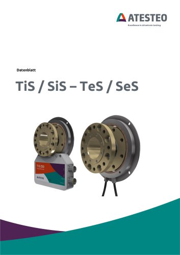 Datenblatt TiS Z50
20 Seiten
 Handbuch T-Serie
132 Seiten
 Datenblatt TeS Z50
21 Seiten
 Handbuch RT11-Serie
132 Seiten
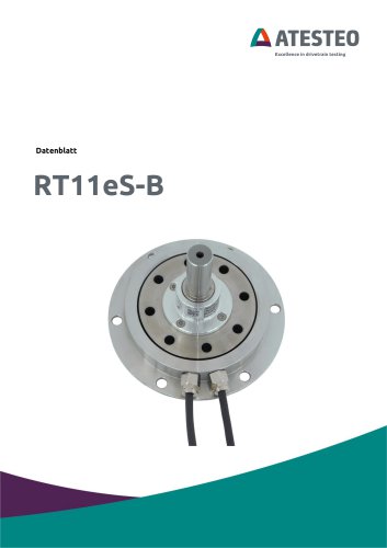 Datenblatt RT11eS-B
20 Seiten
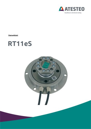 Datenblatt RT11eS
17 Seiten
 Handbuch HSTTeS-Serie
132 Seiten
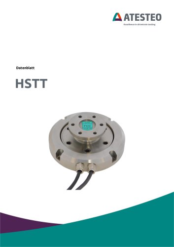 Datenblatt HSTTeS-Serie
20 Seiten
 Datenblatt F23 RTS
7 Seiten
 Datenblatt F3 RTS
7 Seiten
 Datenblatt F5xS
18 Seiten
 Datenblatt F34xS
21 Seiten
 Datenblatt F3xS
27 Seiten
 Datenblatt F23xS
21 Seiten
 Handbuch Fx-Serie
132 Seiten
 Datenblatt F2xS
35 Seiten
 Datenblatt F1xS
27 Seiten
 Datenblatt F0xS
51 Seiten
 Datenblatt F0xS-SV
27 Seiten
 Datenblatt DF RTS
11 Seiten
 Datenblatt DF plus HS
20 Seiten
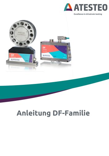
 Handbuch DF plus-Serie
132 Seiten
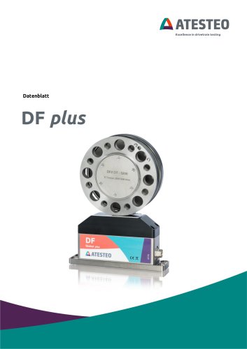 Datenblatt DF plus-Serie
41 Seiten
 Handbuch DF dual-Serie
132 Seiten
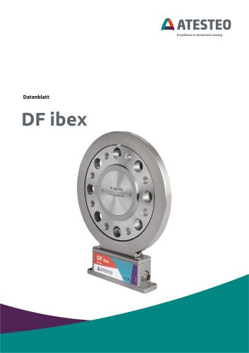
 Handbuch DF ibex-Serie
132 Seiten
 Datenblatt DF3 ibex
21 Seiten
 Datenblatt DF2 ibex
21 Seiten
 Datenblatt DF1 ibex
21 Seiten
- Drehmomentsensor
- Dynamischer Drehmomentsensor
- Rotations-Drehmomentsensor
- Analoger Drehmomentsensor
- Dehnungsmessstreifen-Drehmomentsensor
- DC-Drehmomentsensor
- Kontaktloser Drehmomentsensor
- Digitaler Drehmomentsensor
- Hochpräzisions-Drehmomentsensor
- Drehmomentsensor mit Flanschanschluss
- Modularer Temperaturkontrolle
- Drehmomentsensor mit Spannungsausgang
- Kompakter Drehmomentsensor
- Drehmomentsensor / 12 VDC
- USB-Drehmomentsensor
- Flanschmontage-Drehmomentsensor
- Drehmomentsensor nach Maß
- Drehmomentsensor für Prüfstände
- Drehmomentsensor für Automobilanwendungen
- Drehmomentsensor / 24 VDC