vv

vv
Das Dokument beschreibt das FAFNIR Faseroptik-Überfüllschutzsystem, das Überfüllungen in Lagertanks und Prozessbehältern verhindert. Es umfasst die Modelle LOF 1.1 und LOF 500/NB 220 und bietet Anleitungen zur Installation, Wartung und Fehlerbehebung.
Das System besteht aus einem Füllstandsmelder und einem Messumformer mit Alarm- und Schaltausgang. Es ist wartungsfrei, anpassbar an die Tankgröße und für Ex-Zone 0 verfügbar.
Das System birgt potenzielle Gefahren und darf nur von qualifiziertem Personal installiert werden. Änderungen sind nur mit Zustimmung des Herstellers erlaubt.
Der Füllstandsmelder nutzt Infrarotlicht, das bei Flüssigkeitskontakt gebrochen wird. Der Messumformer wandelt das Signal in ein binäres Ausgangssignal um und signalisiert Betriebszustände optisch und akustisch.
Die Installation erfordert die Ausrichtung des Füllstandsmelders und die Montage des Messumformers. Für Ex-Zonen ist ein Überspannungsschutz notwendig.
Regelmäßige Tests sind erforderlich, um die Funktionalität sicherzustellen. Mindestens einmal jährlich sollte die ordnungsgemäße Funktion überprüft werden.
Das Handbuch bietet Anleitungen zur Diagnose und Behebung von Fehlern. Bei Fehlfunktionen kann die Bestätigungstaste am Transducer NB 220 QS genutzt werden.
Es werden Temperatur- und Druckbereiche, Materialangaben und elektrische Spezifikationen bereitgestellt. Die Schutzklasse variiert je nach Einsatzort.
Die Dokumentation beschreibt verschiedene Typen von Füllstandsmeldern, geeignet für Tanks mit brennbaren Flüssigkeiten. Typencodes geben Aufschluss über Bauart und Sondenrohrdurchmesser.
Die Füllstandsmelder sind für brennbare Flüssigkeiten der Gefahrenklassen AI, AII und B geeignet und können in Zone 0 eingesetzt werden.
Die medienberührten Teile bestehen aus Edelstahl, Aluminiumoxid und FFKM. Flansche können aus Stahl mit beschichteten Dichtflächen gefertigt werden.
Technische Sicherheitsvorschriften wie BetrSichV und VDE sind zu beachten. Für Sensoren mit Steckverbindung ist keine zusätzliche Verkabelung erforderlich.
Die Füllstandsmelder dürfen nur an zertifizierte Stromkreise angeschlossen werden. Maximale Werte sind U0: 24 V, I0: 150 mA, P0: 600 mW.
Die Geräte sind gemäß der EG-Richtlinie 94/9 zertifiziert und tragen die EC-Prototypenzertifikatsnummer TÜV 03 ATEX 2171.
Der Messumformer wandelt das Signal des Füllstandsmelders in ein binäres Ausgangssignal um und bietet Funktionen wie Alarmrelais.
Die Installation muss spritzwassergeschützt erfolgen, und die Geräte dürfen nur außerhalb explosionsgefährdeter Bereiche aufgestellt werden.
Katalogauszüge
Overfill Protection System LOF 1.1 and LOF 500/NB220Page 4/43 >
Katalog auf Seite 4 öffnen
The overfill protection system has been developed, manufactured and tested inaccordance with the state of the art and the recognised rules of safety engineering. Nevertheless, it could be hazardous. Therefore, please observe the following safety instructions. > The safety instructions contained in this manual are highlighted as follows: If you fail to observe these safety instructions, there will be a risk ofan accident or the LOF1.1.., LOF500../NB220.. overfill protection system may be damaged. Useful information to ensure that the overfill protection system operatesproperly or make your work...
Katalog auf Seite 5 öffnen
Overfill Protection System LOF 1.1 and LOF 500/NB220Page 6/43 >
Katalog auf Seite 6 öffnen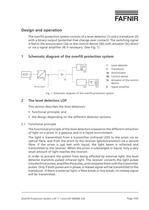
1 Level detector 2 Transducer > Eu 3a Annunciator 3b Control device > (1)(2)(3a)(3b)(3c)Binary signal(4) 3c Actuator of the controldevice 4 Signal amplifier Fig. 1: Schematic diagram of the overfill protection system > Overfill Protection System LOF 1.1 and LOF 500/NB220Page 7/43 >
Katalog auf Seite 7 öffnen
2.2General designThe level detectors consist of a probe tube, which reaches into the tank andcarries a sensor, protected against mechanical damages, on its bottom end. The corresponding probe length is permanently imprinted at the top end of the probe.2.2.1Level detector LOF1.11..This level detector is the LOF standard version and can be used in almost allapplication areas. The transducer electronics are installed in a stainless steel housing located directly on the probe tube (see Fig.2a2d).The level detector can optionally be equipped with an electric plug-in connectionfor a comfortable connection...
Katalog auf Seite 13 öffnen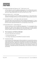
2.2.5Height-adjustable level detector LOF..E with screw-in unitLOF level detectors with the additional designation "E" are fitted with a screw-in unit, which is used to adjust the probe tube and the response length to a particular height depending on the tank size (see Fig.2a, 2c, 2e).2.2.6Level detector LOF..F with flangeWith LOF level detectors with the additional designation "F" the probe tube iswelded to the flange and thus can not be adjusted in height (see Fig.2b, 2d, 2f).2.2.7Level detector LOF..S with larger probe tube diameterThe probe tube of LOF level detectors with the additional...
Katalog auf Seite 14 öffnen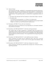
Overfill Protection System LOF 1.1 and LOF 500/NB220Page 15/43 >
Katalog auf Seite 15 öffnen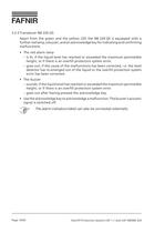
3.2.5Transducer NB220QSApart from the green and the yellow LED the NB220QS is equipped with afurther red lamp, a buzzer, and an acknowledge key for indicating and confirming malfunctions:The red alarm lampՖis lit, if the liquid level has reached or exceeded the maximum permissibleheight, or if there is an overfill protection system error.goes out, if the cause of the malfunctions has been corrected, i.e. the leveldetector has re-emerged out of the liquid or the overfill protection system error has been corrected.֕The buzzersounds, if the liquid level has reached or exceeded the maximum permissibleheight,...
Katalog auf Seite 16 öffnen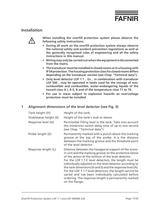
When installing the overfill protection system please observe thefollowing safety instructions: During all work on the overfill protection system always observethe national safety and accident prevention regulations as well asthe generally recognised rules of engineering and all the safetyinstructions in this manual. Օ Wiring may only be carried out when the equipment is disconnectedfrom the mains. The transducer must be installed in closed rooms or in a housing withIP 54 protection. The housing protection class for closed rooms differsdepending on the transducer version (see Chap."Technical...
Katalog auf Seite 17 öffnen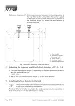
H Tank height S Stub/sleeve height A Response level Z Probe length L Response length Y Reference dimension Fig.3: Alignment dimensions of the level detector > Overfill Protection System LOF 1.1 and LOF 500/NB220Page 18/43 >
Katalog auf Seite 18 öffnen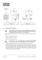
Connectionto transducer Connection to transducer: 1 (brown) + 3 (blue) Fig.4b: Connecting level detector LOF..SteckDD28 plug(counter plug not included in scope of delivery)Fig.4c: Connecting level detector LOF..M12M12 plug(counter plug not included in scope of delivery) The transducer may only be set up outside the area subject toexplosion hazards. The housing protection class differs depending onthe transducer version (see Chap."Technical data"). The length of cable from the level detector to the transducer must not be morethan:250 m in the case of 0.5mm > 2 Օ500 m in the case of 1 mm > 2 750...
Katalog auf Seite 20 öffnen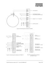
Level detectorLevel detector output,to annunciator/control deviceOutput "S" or "Z" (option)Auxiliary power Fig.4d: Connecting the transducer LOF500 > d2, z2: Level detector 1d8, z8:Level detector 2d18, d20, d22:Level detector 1 outputd24, d26, d28:Level detector 2 outputd/z30, d30, z32:Auxiliary power d2, d4:Level detectord16, d18, d28:Level detector output, to annunciator/control deviced22, d24, d26:Output "S" or "Z" (option)d/z28, d30, d32:Auxiliary power Fig.4f: Connecting the transducerLOF50019"Duo Overfill Protection System LOF 1.1 and LOF 500/NB220Page 21/43Fig.4e: Connecting the transducer...
Katalog auf Seite 21 öffnen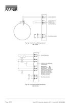
Level detectorLevel detectoroutput, to annunciator/ control device Auxiliary power Level detectorOptions for externalconnection Attention: Outputs are energised! External annunciators and control devices must be connected between terminals 4 and 8 to monitor auxiliary power! Auxiliary power >
Katalog auf Seite 22 öffnen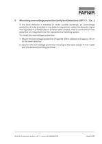
If the level detector is installed in tanks outside buildings, an overvoltageprotection is to be provided in the detector signal line, unless the detector signal line is guided in a metal tube or a metal cable conduit, that is connected to tank potential or integrated into the equipotential bonding system.To install the overvoltage protection:1.Mount the overvoltage protection of type BA350 in a distance of approx.50cmto the level detector.2.Connect the overvoltage protection housing to the tank using a 4-mm > 2 -cableand the external earthing terminal. > Overfill Protection System LOF 1.1 and...
Katalog auf Seite 23 öffnen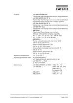
C to +50 а CHousing protection class:In enclosed rooms:LOF500, LS500S/Z, NB 220 H/QS: IP 40 LOF50019"..:IP20 In the field: IP54Dimensions:LOF500, LS500S, LS500Z:150x75x110LOF50019"..:160x100, 7TE, 3HE,DIN41612F, European PCBNB 220 H:110 x 51 x 110 NB 220 QS:150 x 75 x 110 AC: ≤ 250 V, ≤ 4 A, cos ϕ ≤ 0.7, 500 W max.DC: Change-over contact carrying capacity: Pump, solenoid valve, etc. (terminal4, 8): 230 V, 50 Hz, 50 W max. External lamp (terminal5, 8): 230 V, 50 Hz, 100 W max. External acknowledge key (terminal5, 7): 230 V, 50 Hz External horn (terminal9, 8): 230 V, 50 Hz, 50 W max.Ambient temperature:-25...
Katalog auf Seite 27 öffnenAlle Kataloge und technischen Broschüren von FAFNIR GmbH
 TORRIX M12 MOBILE
2 Seiten
 TORRIX XTS
2 Seiten
 SEPARIX
8 Seiten
 Prozessautomation
28 Seiten
 O²-PID
4 Seiten
 COMS Leaflet
2 Seiten
 Wallmounting Typ 907
4 Seiten
 QE 200
4 Seiten
 76 / NB 220
2 Seiten
 UM 2.1/2.2/2.3
20 Seiten
 TORRIX HART
28 Seiten
 TORRIX M12
8 Seiten
 LS 300 / 500
7 Seiten
 76 A / NB 220
5 Seiten
 SECON-X
4 Seiten
 PRESSURIX
12 Seiten
 LOGI-System
12 Seiten
 Insite360
4 Seiten
 Plugs
Plugs12 Seiten
 UM 2.1/UM 2.2/UM 2.3
20 Seiten
 TORRIX-HART
28 Seiten
 DIVELIX
8 Seiten
 CONDURIX-HART
28 Seiten
 CONDURIX
24 Seiten
 VAPORIX
12 Seiten
 VISY-X
24 Seiten
 Zubehör
3 Seiten
 VISY-Command Web
4 Seiten
 VISY-Reed
4 Seiten
 VISY-RF
2 Seiten
 VISY-Stick
15 Seiten
 VISY-TD Display
2 Seiten
 VISY-View Touch
2 Seiten
 VPI - VISY-Power Interface
1 Seite
 TORRIX
10 Seiten
 TORRIX CI
1 Seite
 TORRIX RS485
3 Seiten
 UM-X Transducer
3 Seiten
 TEMPERIX
8 Seiten
 Overfill Prevention & Accessories
12 Seiten
 VISY-Input VISY-Output
4 Seiten
 VISY-Command
5 Seiten
 LPG-Sensoren
8 Seiten
 TORRIX 6
1 Seite
 LPG Sensors
8 Seiten
 VAPORIX Flow and Control
40 Seiten
 TORRIX RS485 Modbus
16 Seiten
 FAFNIR Hart Setup
9 Seiten


Archivierte Kataloge
 HPH Ex d
3 Seiten
 VISY-Monitor
2 Seiten
 2020 VISY-Stick Flex
2 Seiten
 2016 VISY-Stick Flex
2 Seiten
 76/NB 220 - ÜBERFÜLLSICHERUNG
33 Seiten
 VISY-X LON
10 Seiten
 81 D-Ex Grenzwertgeber
35 Seiten
 Wandarmatur 907 Z
2 Seiten
 SEPARIX
58 Seiten
 VAPORIX PCM
7 Seiten
 VAPORIX Service Dongel
22 Seiten
 VAPORIX Flow/Control
34 Seiten
 VISY-Setup V 3.1.0
42 Seiten
 VISY-Setup V2.10
43 Seiten
 VISY-View
24 Seiten
 VISY-Stick und VISY-Command
24 Seiten
 83 UV/84 UVT Grenzwertgeber
29 Seiten
 Grenzwertgeber und QSS-Anschlussarmatur
12 Seiten


- Liebherr Display
- Liebherr Temperatursensor
- LCD-Anzeigetafel
- Industrie-Anzeigetafel
- Liebherr Niveauschalter
- Liebherr Niveauschalter für Flüssigkeiten
- Liebherr Füllstandsensor
- Liebherr Füllstandsensor für Flüssigkeiten
- Analoger E/A
- Runder Stopfen
- Liebherr Schnittstellen-Software
- Liebherr Thermoelement
- Liebherr analoger Füllstandsensor
- Display-System / Kontroll
- Liebherr automatisches Prüfgerät
- Liebherr Edelstahl-Niveauschalter
- Liebherr Leckdetektor
- Netzwerk-Software
- Liebherr Füllstandsensor mit Digitalausgang
- Informationsanzeigetafel