Kolbenstangenloser Zylinder mit Kugelumlaufführung
1 /6Seiten
Kolbenstangenloser Zylinder mit Kugelumlaufführung
1 /6Seiten
Katalogauszüge

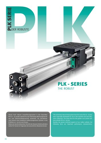
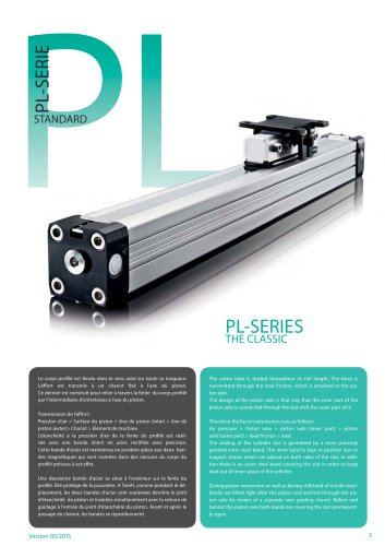
PLK SERIE PLK DER ROBUSTE PLK - SERIES THE ROBUST Dieses hoch robuste Linearführungssystem in den Baureihen PLK 16 – 63 wurde speziell für die Anwendung Werkzeugmaschinen und Industrierobotertechnik entwickelt. Als Antriebselement kommt unser bewährter kolbenstangenloser Zylinder in den Ø-Reihen 16 – 63 mm zum Einsatz. Neben der bereits bekannten Technik des linearen Arbeitszylinders (siehe PLF-Serie) im Folgenden die wesentlichen Modulmerkmale. 44 This extremely robust linearsystem from the series PLK 16 – 63 has been especially developed for use in the machine tool and robototics industries. The move force for this guide is our proven rodless cylinder PLF 16 – 63 mm. Besides the proven technical aspects of our rodles cylinder, the following facts are important performance characteristics.
Katalog auf Seite 1 öffnen
VORZÜGE/BENEFITS Hohe Tragzahl Schmiernippel allseitig möglich Hohe statische Belastbarkeit für alle Richtungen Führungsschiene im Laufbahnbereich gehärtet und allseitig geschliffen Ruhiger, geschmeidiger Lauf Kugeln aus Wälzlagerstahl Robuste Kugelabdeckung Problemlose Austauschbarkeit high loading characteristics high static loading in all directions quiet and smooth running robust bearing housing easy access to grease nipple hardened and grinded guiderail low friction bearing easy interchangeability TECHNISCHE DATEN / TECHNICAL DATAS Bauart Kolbenstangenloser...
Katalog auf Seite 2 öffnen
R S U T ( A + Hub / stroke / course ) ± 0,5 B + Hub / stroke / course C D B M1, N M Z2 O Q x Q1 P1 W2 J H VH Ko WH Mr L Ma G Mv (Hub / Stroke / course + 2 x A) ± 0,5 S YK H Q x Q1 C PLF 40-63 PLF 16-32 PLF 50-63 A J S U W2 Formeln YH YH Y WH Luftanschlüsse Air connections M1, N WH L ha W3 hv hr Y W2+W3 W1 YS P P W4 PLF 16-40 W3 PL 32-40 PL 16-25 W1 W1 Luftanschlüsse Air connections YS Y WH F K W1 W2 W1 V3 Y VH Ko M, N V3 P-P1 P1 Z2 Z-Z* Z1 W3 P-P1 Z1 M Z-Z* U PL 32-40 E WS S W3 T PL 40-63 PL 16-32 C R B SL F Mr = F * hr U Q 5 4 L Nur bei PLF 32 Kolben 10 E y Ma = F * ha G L D 3 2 M, N1 0,1 Mv...
Katalog auf Seite 4 öffnen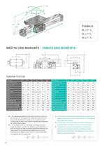
R S U T ( A + Hub / stroke / course ) ± 0,5 B + Hub / stroke / course C D B S E M1, N M Z2 F J O W2 Q x Q1 P1 K W1 W2 W1 V3 M, N V3 P-P1 P1 Z2 Z-Z* Z1 W3 P-P1 Z1 M Z-Z* U W3 T PL 32-40 PL 40-63 PL 16-32 C R H VH VH Y Y Mr Ko WH Ma Luftanschlüsse Air connections L Ko WH Mv G (Hub / Stroke / course + 2 x A) ± 0,5 J S U W3 W1 W1 Formeln W2 W3 YH YH Y WH Luftanschlüsse Air connections Ma = F * ha G L F D y B E SL Mr = F * hr U Q 5 4 L Nur bei PLF 32 Kolben 10 0,1 0,4 6 1 SL Mv = F * hv 3 2 M, N1 M1, N WH L ha Y W2+W3 W1 P YS hv WS P W4 PLF 16-40 hr S YK H Q x Q1 C PLF 40-63 PLF 16-32 PLF 50-63 A...
Katalog auf Seite 5 öffnen
LINEARMODUL PLK / LINEAR UNIT PLK • • • • Stellenangaben bei Hubfestlegung ( 0100-5700 mm ) • • • • Ident-figures for stroke definition ( 0100-5700 mm ) Typen Ident.-Nr. Types Ident.-Nr. Description 71.691. • • • • Ausführungen Uno Rodless cylinder PLF16 Linear unit PLK16.1 PLK16.1 71.691. • • • • Uno Linearzylinder PLF16 Lineareinheit PLK16.2 71.692. • • • • Tandem Linearzylinder PLF16 Lineareinheit PLK16.2 71.692. • • • • Tandem Rodless cylinder PLF16 Linear unit PLK25.1 72.591. • • • • Uno Linearzylinder PLF25 Lineareinheit PLK25.1 72.591. • • • • Uno Rodless cylinder PLF25 Linear unit PLK25.2...
Katalog auf Seite 6 öffnenAlle Kataloge und technischen Broschüren von MEDAN
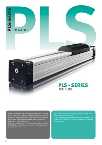 PLS - Der Gleiter
5 Seiten
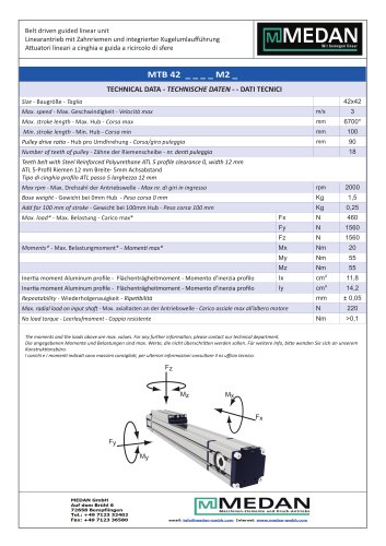 Linearzylinder Serie MTB42
2 Seiten
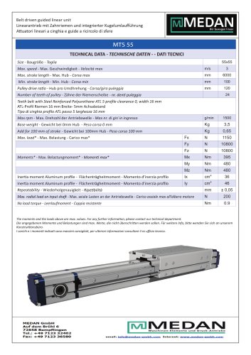 Linearzylinder Serie MTS55
2 Seiten
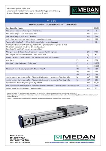 Linearzylinder Serie MTS80
2 Seiten
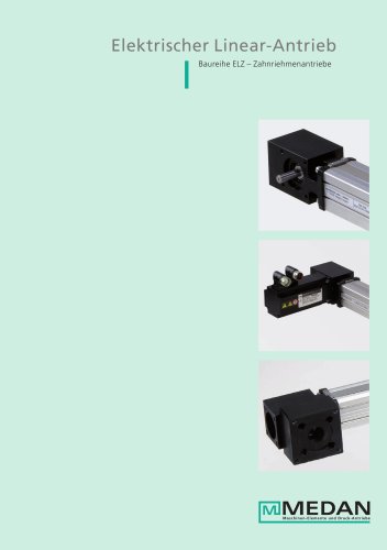
 Elektrischer Linear-Antrieb
16 Seiten
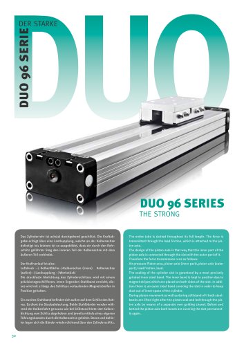 Duo96 Serie
8 Seiten
 Medan Katalog 2012
70 Seiten
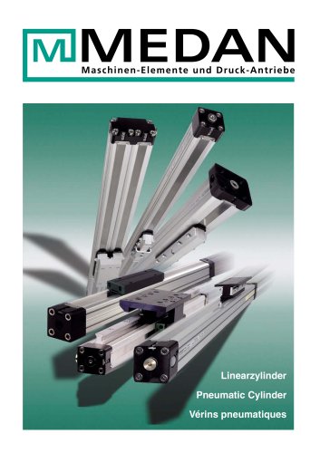 Linearzylinder
44 Seiten
 Elektrischer Linear-Antrieb
16 Seiten
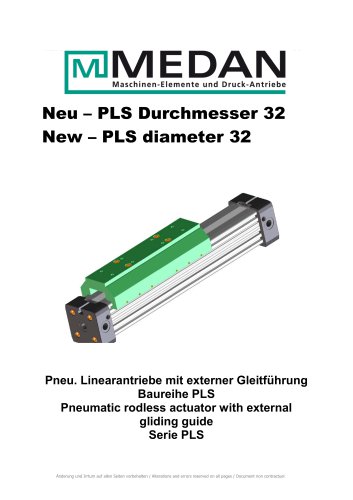 New – PLS diameter 32
4 Seiten
 GANTRY FOR MANIPULATOR
9 Seiten
 AW-SERIE
8 Seiten
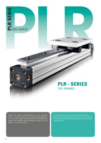
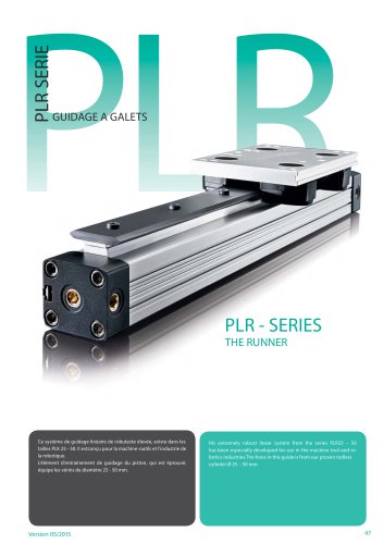 PLR - SERIES
6 Seiten
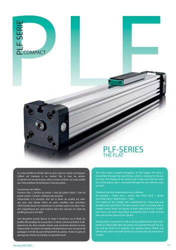 PLF-SERIES
11 Seiten
 PL-SERIES
11 Seiten
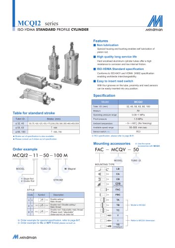 MCQI2 series
11 Seiten
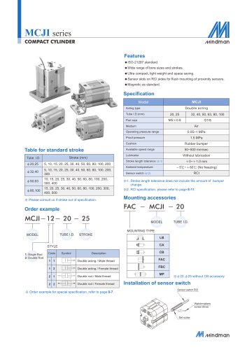 MCJI series
7 Seiten
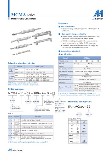 MCMA series
13 Seiten
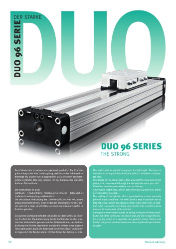 DUO 96 SERIES
8 Seiten
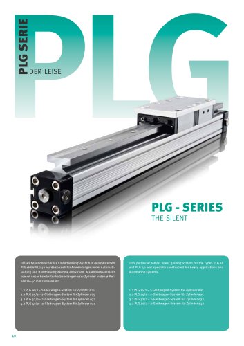
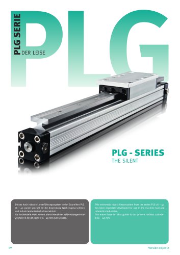 PLG - SERIES
4 Seiten
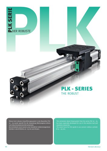 PLK - SERIES
6 Seiten
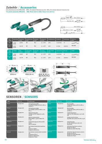 Accessories
2 Seiten
Archivierte Kataloge
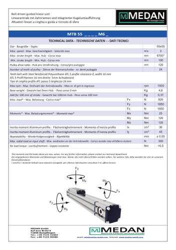 Linearzylinder Serie MTB55
2 Seiten
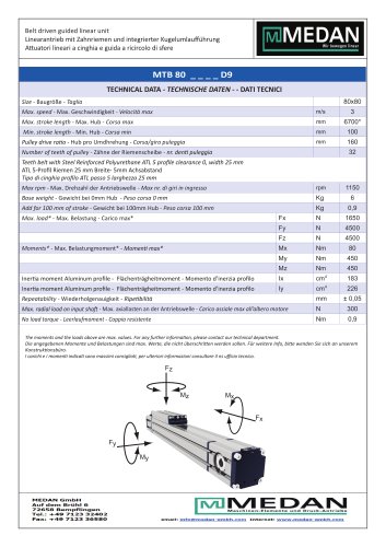 Linearzylinder Serie MTB80D9
2 Seiten
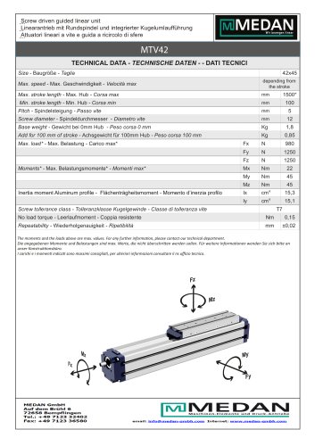 Linearzylinder Serie MTV42
2 Seiten
 Linearzylinder Serie MTV55
2 Seiten
 Linearzylinder Serie MTV80
2 Seiten
- Antrieb
- Linearantrieb
- Elektrischer Antrieb
- Doppeltwirkender Zylinder
- Pneumatikzylinder
- Einfachwirkender Zylinder
- Aluminiumlegierungszylinder
- Präzisionsantrieb
- Elektrozylinder
- Pneumatischer Antrieb
- Doppeltwirkender Antrieb
- Kolbenstangenzylinder
- Schrauben-Zylinder
- Riemengetrieben-Antrieb
- Geführter Antrieb
- Kugelgewindespindel-Zylinder
- Drehzylinder
- Geführter Zylinder
- Kolbenstangenloser Antrieb